Interface and Application Programming: Stay Connected!
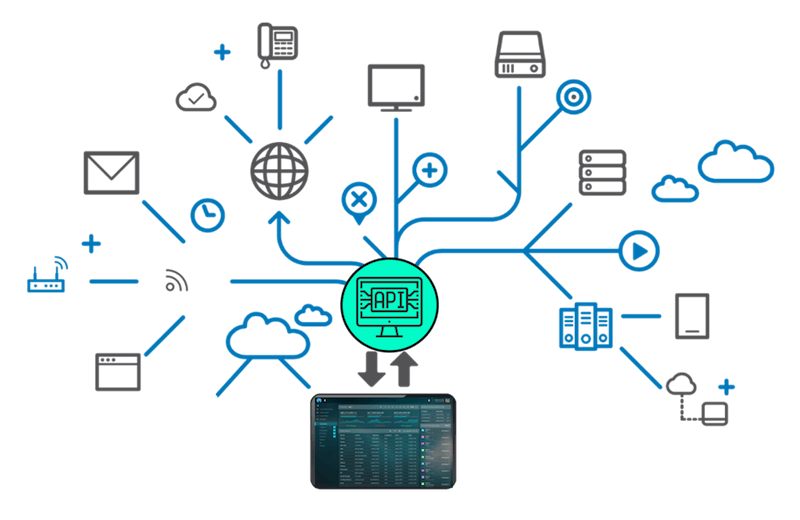
In this assignment we are suppose to create an interface to control or monitor our hardware. For this assignment I decided to use Blynk which is a hardware-agnostic IoT platform with customizable mobile apps, private cloud, device management, analytics, and machine learning, together with NodeMCU to establish a coomunication between the App and several stepper motors.
System Overview
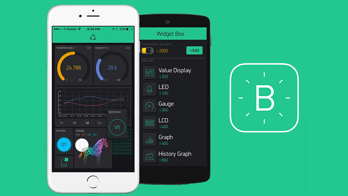
Before starting the process it is important to explain more about the logic behind the two technologies I am going to use. Blynk is an app that gives you the space to create your own App interface or IoT platform to connect your devices to the cloud, and analyze telemetry data. Blynk App - allows to you create amazing interfaces for your projects using various widgets they provide. Blynk Server - responsible for all the communications between the smartphone and hardware. You can use our Blynk Cloud or run a private Blynk server locally.
On the other hand, NodeMCU is an open source IoT platform. It includes firmware which runs on the ESP8266 Wi-Fi SoC from Espressif Systems, and hardware which is based on the ESP-12 module. It is Arduino-like hardware IO, it has advanced API for hardware IO, which can dramatically reduce the redundant work for configuring and manipulating hardware. Code like arduino, but interactively in Lua script.
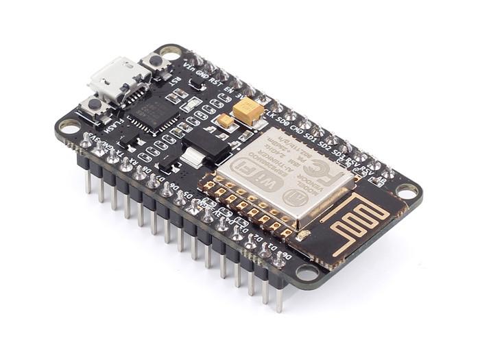
For this assignment I am going to use the NodeMCU Amica which is a ESP8266 Wifi Module based development board. It has got Micro USB slot that can be directly connected to the computer or other USB host devices to program it using Arduino IDE.
Software Setups
I downloaded the app from the App store, I signed up, with my email, which is an important step since the application will going to send you very important informations related to any interface you create using Blynk.
After sigining up I breated a new project and choosed ESP8266 as the device I am going to connect with the application.
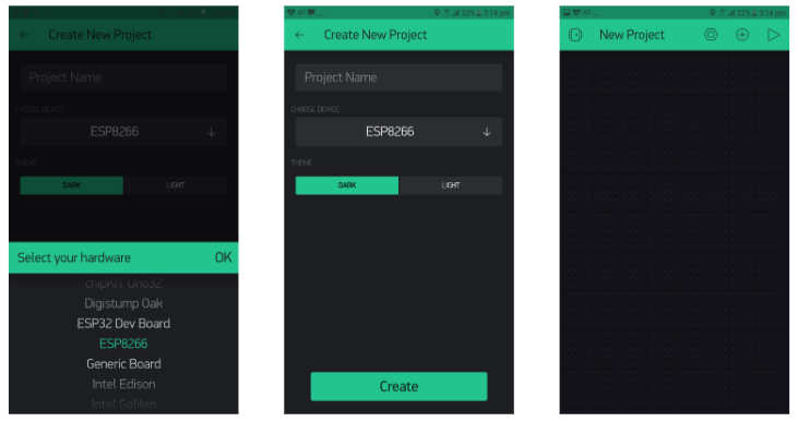
When you create the project, I received an email from Blynk. This email has the Auth Token of the project. The Auth Token is very important I will need it later to stick it into your ESP8266’s firmware. Then after creating the new project I start adding a widget to my interface. These widgets are the one I am going to use to control the stepper motor.
I started with adding a Joystick, and I set the pin for the joystick to be Virtual pin 0.
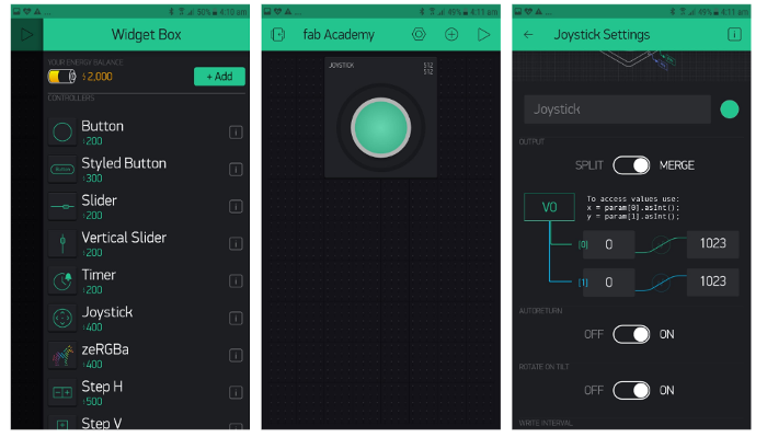
Then I added two buttons to control the motor to left and write and I setted the buttons pins to virtual pin 1 and virtual pin 2, for the left and the right button respectively.
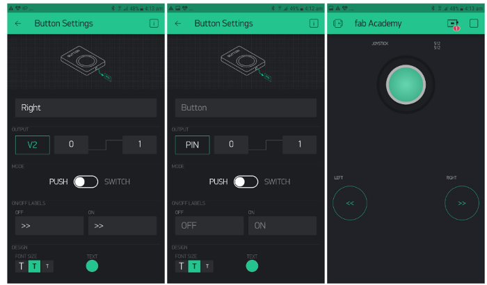
And this is basically my interface that I am going to use to control my stepper motor. Now the second things to do is to move to Arduino IDE to set up the code that I am going to use with the interface.
Before start the code it is imporatnt to install Blynk Arduino IDE library, and ESP8266 Arduino IDE to be able to work with both with Arduino IDE.
The interface code is the following:
#define BLYNK_PRINT Serial
#include
#include
#include

char auth[] = "e7582ed2151747a9818004b519e4d1a8";
char ssid[] = "---";
char pass[] = "----";

// change this to fit the number of steps per revolution
const int stepsPerRevolution = 200;

Stepper myStepper(stepsPerRevolution, 2, 3, 4, 5);


int xVal=512;
void setup() {

   Serial.begin(9600);
   Blynk.begin(auth, ssid, pass);
}
void loop() {

 Blynk.run();

  if( (xVal < 500)  ){
     myStepper.step(1);
     delayMicroseconds(3000);
  }else if( xVal > 550){
     myStepper.step(-1);
     delayMicroseconds(3000);
  }


}
BLYNK_WRITE(V1)
{
  xVal = param[0].asInt();
 // int y = param[1].asInt();
}
BLYNK_WRITE(V2)
{
   if( param.asInt() == 1){
        xVal = 0;
   }else{
        xVal = 512;
   }
}
BLYNK_WRITE(V3)
{
   if( param.asInt() == 1){
        xVal = 1000;
   }else{
        xVal = 512;
   }
}
It is important to pay attention to Auth Token which is the pin Blynk is going to send an email with for you when creating a new project. And also you should include your WiFi user name and password to the code to establish the connections between the interface and the hardware. Any mistakes in any of these three you will not be able to fully connect your interface to your hardware.

The Hardware settings
As I mentioned above for the hardware I am going to control a stepper motor using a NodeMCU ESP8266. The connections between the hardware and the software is quite easy and similar to normal comercial arduino board. You can find the connection below:
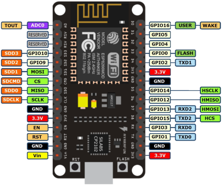
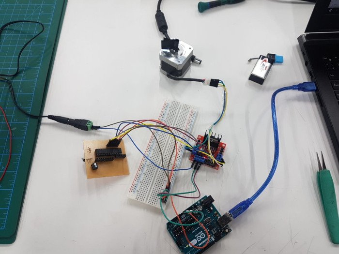
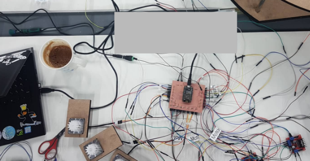
I connected my stepper motor to the motor driver and to external power supply. and then I connected the input pins(IN1, IN2, IN3 and IN4) of the L298N module to four Digital pins of NodeMCU ESP8266. The following picture shows the connections.
Testing
Finally the system testing:
output circuit
The next stage of this assignment is to connect either the input or output circuit to an interface to either read data (input device) or to control a device (output device). For this assignment I decided to use my output circuit to control it using an interface.
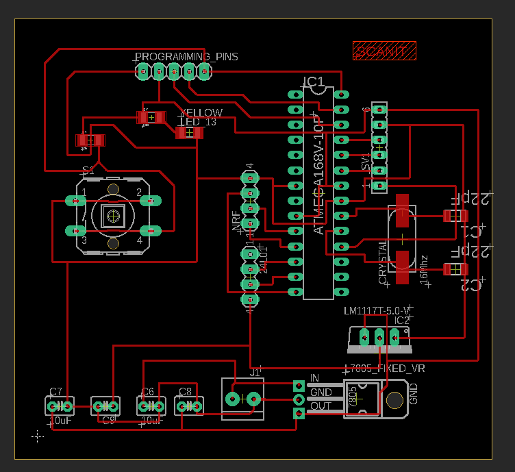
I connected my stepper motor to the motor driver and to external power supply. and then I connected the input pins(IN1, IN2, IN3 and IN4) of the L298N module to four digital pins of my ATMEG32-P (Pin 2, 3,4, and 5). Then using Blynk I will control the stepper motor.
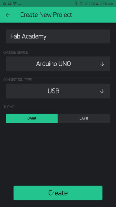
Starting from Blynk, I choosed my device to be Arduino Uno, and the way to connect blynk with the circuit is using USB.
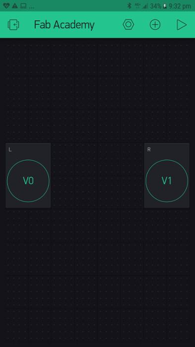
Then in the interface, I added two buttons left and right, connected to virtual pin 0 and virtual pin 1, respectively.
Then in Arduino IDE I uploaded the following code to the ATMEG32-P. This code will enable the connections between my hardware and interface.
// Include the Arduino Stepper Library
#include <Stepper.h>
#define BLYNK_PRINT DebugSerial


// You could use a spare Hardware Serial on boards that have it (like Mega)
#include <SoftwareSerial.h>
SoftwareSerial DebugSerial(2, 3); // RX, TX

#include <BlynkSimpleStream.h>

// Number of steps per output rotation
const int stepsPerRevolution = 200;

// Create Instance of Stepper library
Stepper myStepper(stepsPerRevolution, 2, 3, 4, 5);

// You should get Auth Token in the Blynk App.
// Go to the Project Settings (nut icon).
char auth[] = "OHyzbyWDHRRTmChFJG38m2xhqhxWAyzP";
int xVal=512;

void setup()
{
  // Debug console
  DebugSerial.begin(9600);

  // Blynk will work through Serial
  // Do not read or write this serial manually in your sketch
  Serial.begin(9600);
  myStepper.setSpeed(60);
  Blynk.begin(Serial, auth);
}

void loop()
{
  Blynk.run();
}


BLYNK_WRITE(V0)
{
   if( param.asInt() == 1){
       myStepper.step(-stepsPerRevolution);
   }
}
BLYNK_WRITE(V1)
{
   if( V1 == 1){
  myStepper.step(stepsPerRevolution);
}
}
Then I went to Document > Arduino > Libraries > Blynk > Script. In the script folder there is a file called "blynk-ser"
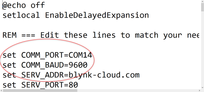
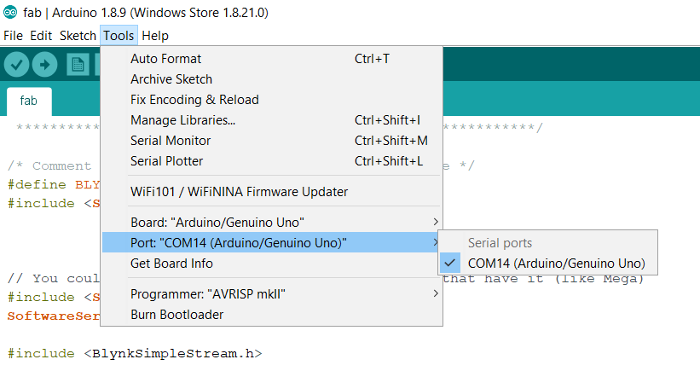
In this folder I changed the COM-PORT to where my Arduino is connected to. To double check the COM-PORT, I went to Arduino IDE and saw the port number from Tool > port.
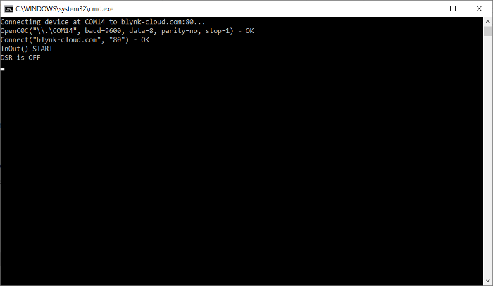
Then I closed Arduino IDE and run the script file "blynk-ser" and I opened Blynk and run the program. Here is the screenshots of the script file.
Finally I tested the program with Blynk interface and here is the final results.
